How to Read Oil and Gas P&ID Symbols Kimray
P&ID Symbols and Standards. P&ID symbols follow standardized conventions set by organizations such as the International Organization for Standardization (ISO) and the American National Standards Institute (ANSI). These symbols ensure consistency and universal understanding across industries and regions. Evolution of Piping and Instrumentation.
Standard P&ID Symblos Legend Industry Standardized P&ID Symbols
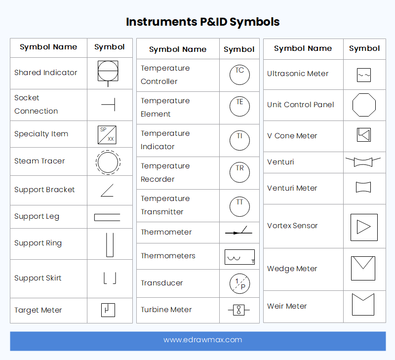
Piping and Instrumentation Diagrams (P&IDs) use specific symbols to show the connectivity of equipment, sensors, and valves in a control system. These symbols can represent actuators, sensors, and controllers and may be apparent in most, if not all, system diagrams. P&IDs provide more detail than a process flow diagram with the exception of the.
P&ID basic symbols YouTube
P&ID SYMBOLOGY. Piping and Instrumentation Diagram, P&IDs, are detailed drawings used in the process industry that depict piping and process equipment, instrumentation and control devices along with safety systems in place that ensure the process remains running in a safe operational state. Applicable to the complete process life cycle, they.

P&ID Symbols & Abbreviations Piping Analysis YouTube
INSTRUMENT P&ID SYMBOLS www.northridgepumps.com/article-350_piping-pid-symbols
P&ID Symbols and Notation Lucidchart
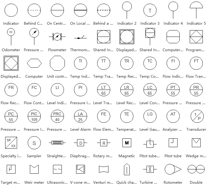
The symbology for the identification of one measurement and control orchestration for the flood and process diagrams and on the P&ID (Piping & Instrument Diagram), commonly called P&I (Piping & Instrumentation), is generally compliant with the Standard ISA (Instrumentation Society of Automation) identified as S.5, that is composed to identificat.
P&ID Process Diagram, Piping, Symbol, Abbreviation, Equipment, Pump, Valve Standard Symbol
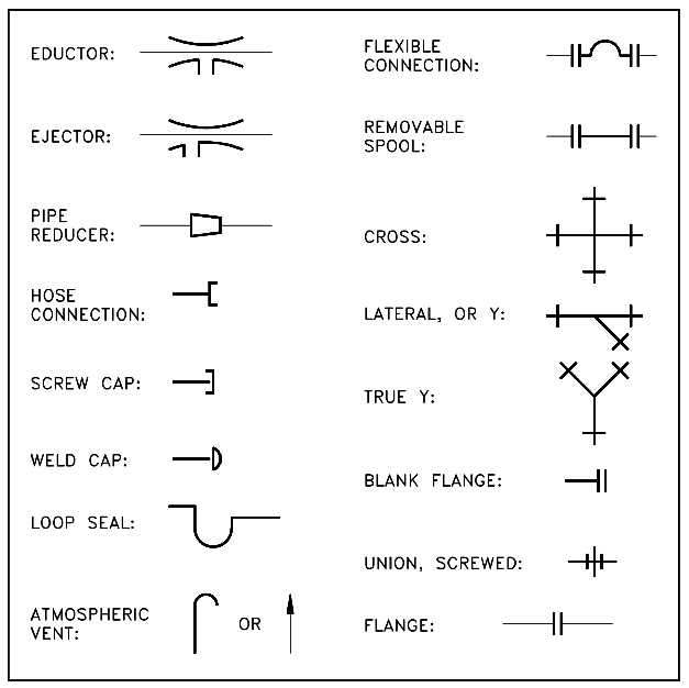
Many common pipe symbols you will see on a typical P&ID are listed in the chart above. Although for most automation projects, these symbols aren't particularly useful as we are more concerned with instrumentation and equipment information. So, on an HMI screen, you will typically only use lines to represent pipes—and not any particular.
Piping and Instrumentation Drawing (P&ID) Tutorials Part 3 (2023)
ISA SYMBOLOGY. The symbology for the identification of and measurement and choose instrumentation on the flow and edit diagrams and on the P&ID (Piping & Instrument Diagram), commonly called P&I (Piping & Instrumentation), is generally compliant with the Standard ISSUS (Instrumentation Society of Automation) identifying as S.5, that is composed of identification codes the graphic symbols.
Piping and Instrumentation Symbols Instrumentation Tools
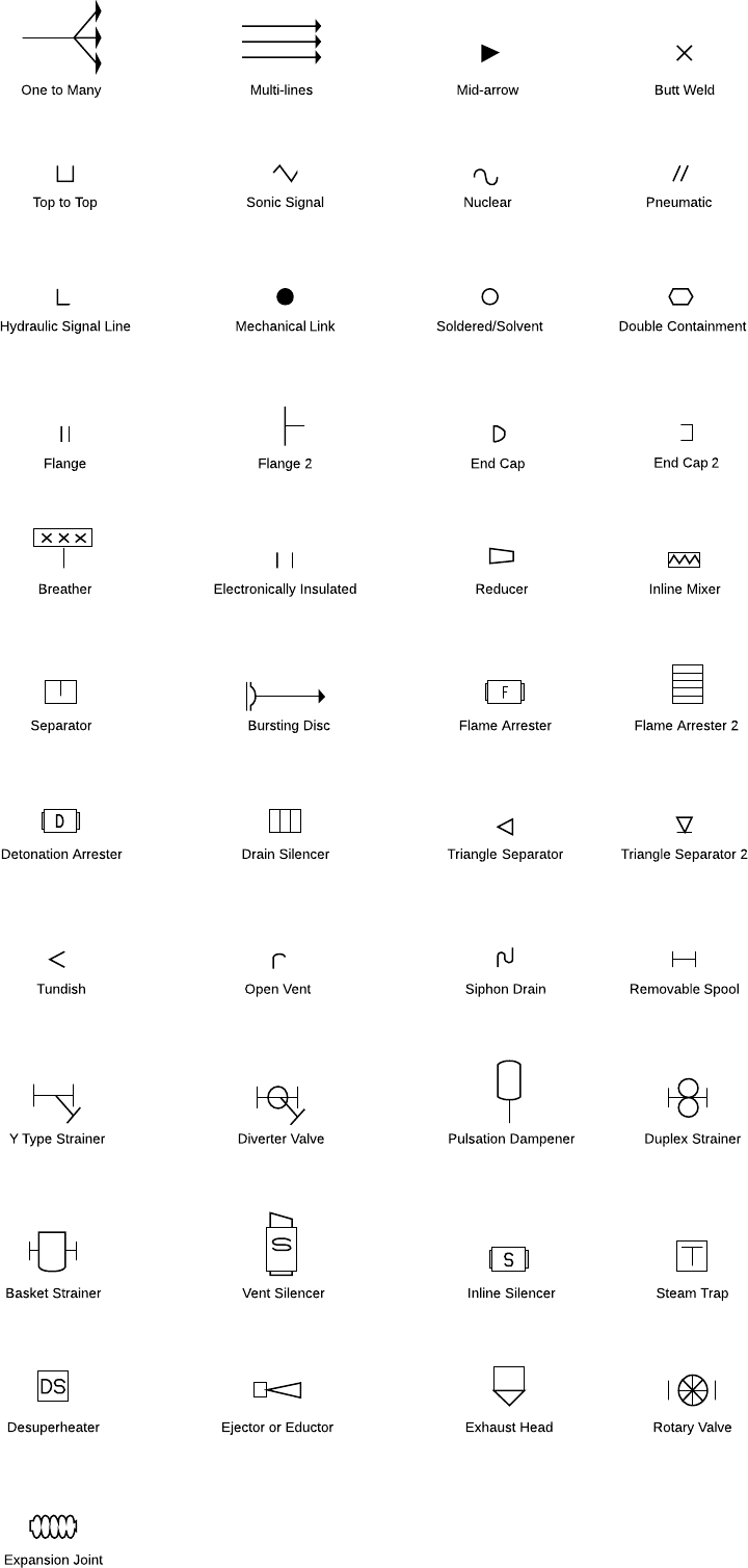
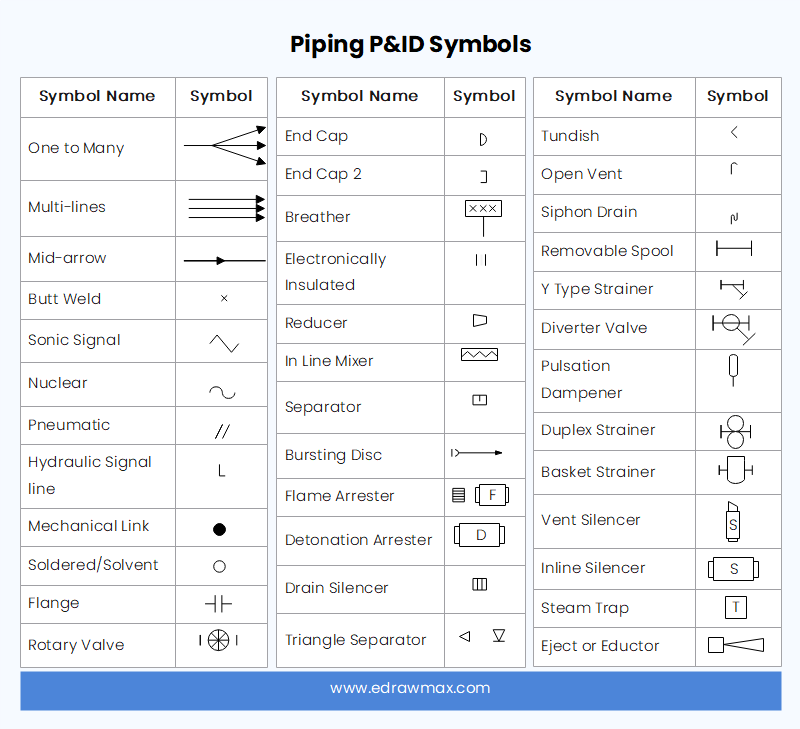
Piping P&ID symbols represent the equipment that transports fluid substances. There are multiple types of pipes that make them eligible for a separate category. It can be simple, multi-line, separators, connectors, end caps, flanges, reducers, and coupling. The list of piping symbols is as follows. Click to download and use this template.
P&ID Symbols and Meanings EdrawMax Online
A piping and instrumentation diagram, or P&ID, shows the piping and related components of a physical process flow. It's most commonly used in the engineering field. Function and purpose of P&IDs P&IDS are foundational to the maintenance and modification of the process that it graphically represents.
What is a Piping and Instrumentation Diagram (P&ID) (2022)
The symbology for the identification of the measurement and control instrumentation on the flow and process diagrams and on the P&ID (Piping & Instrument Diagram), commonly called P&I (Piping & Instrumentation), is generally compliant with the Standard ISA (Instrumentation Society of Automation) identified as S.5, that is composed of identificat.
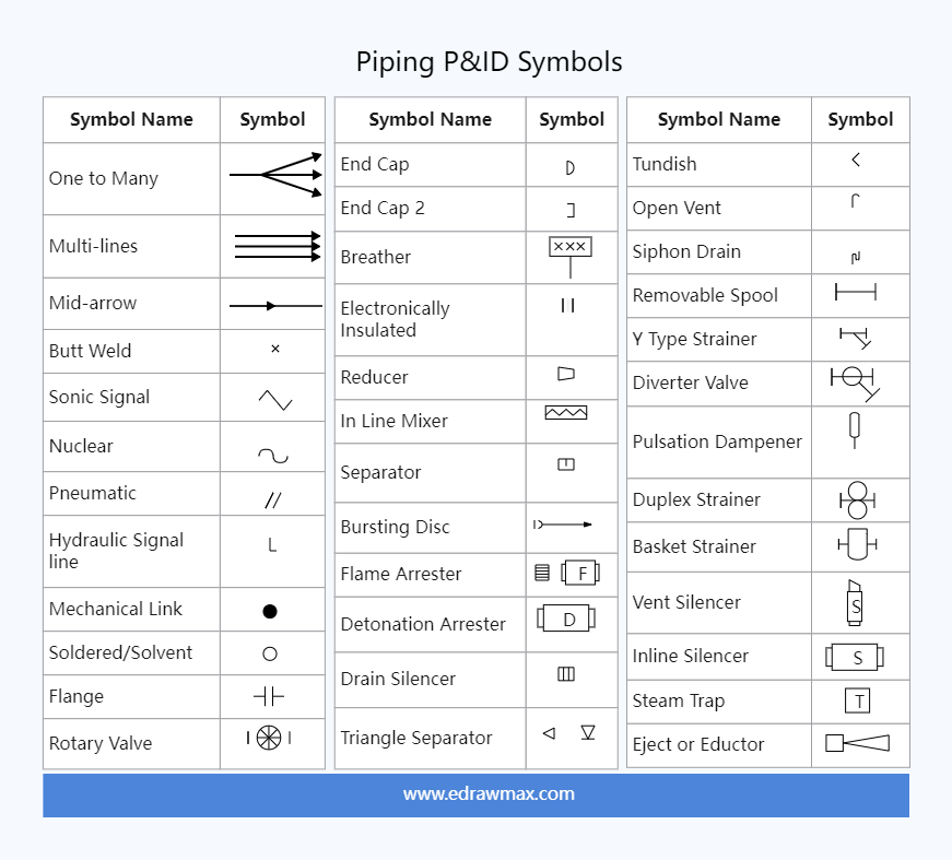
Piping P&ID Symbols EdrawMax Templates
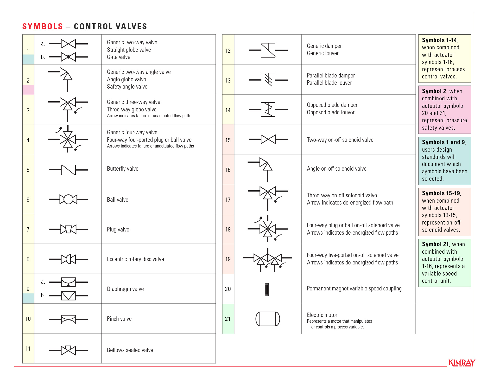
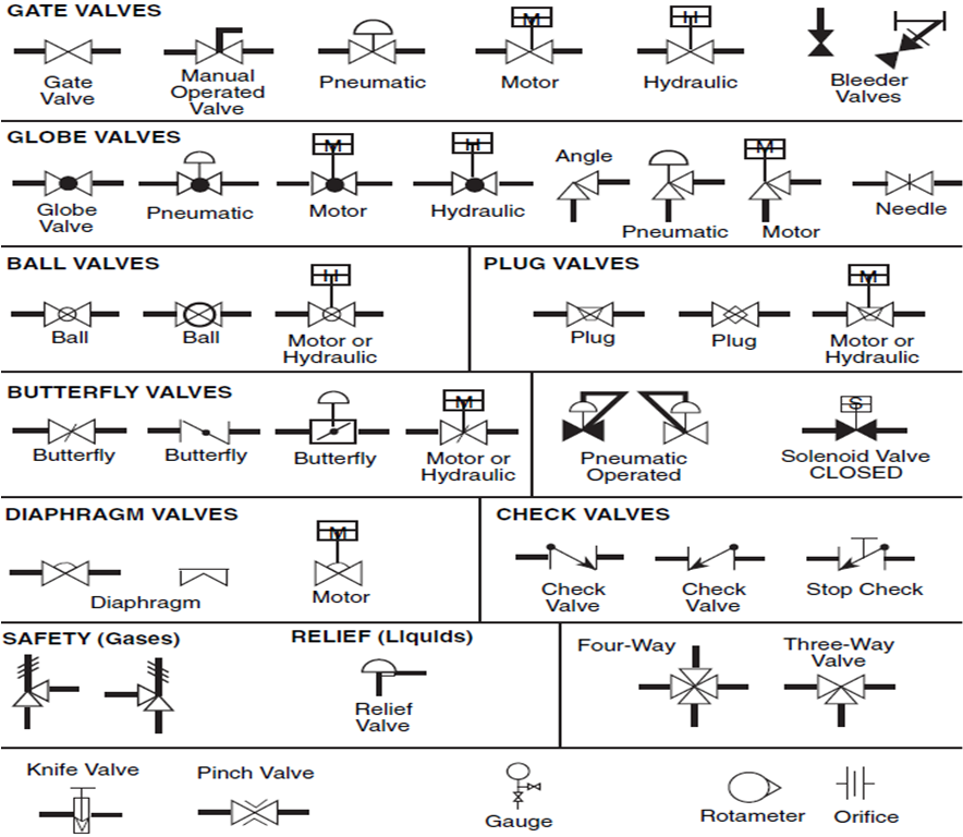
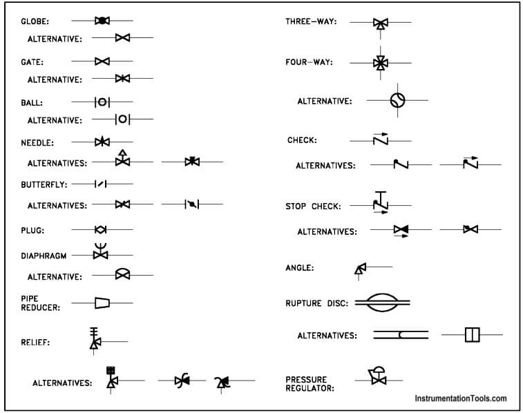
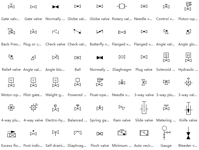
P&ID (Piping and Instrumentation Diagram) vs PFD (Process Flow Diagram). P&ID symbols can sometimes change from company to company. This is especially true with control valve symbols. This chart of common control valve symbols can be downloaded for reference, but always consult the P&ID legend if available..
Easily Learn What is a Piping and Instrumentation Diagram (P&ID)
A P&ID (Also known as PEFS, Process Engineering Flow Scheme) is a fundamental engineering document that serves various purposes as mentioned below. P&IDs Provide key piping and instrumentation items along with their proper arrangement. It serves as a basic document for operation, control, and shutdown schemes.
What is a Piping and Instrumentation Diagram (P&ID) EdrawMax
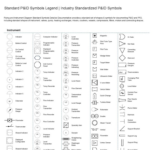
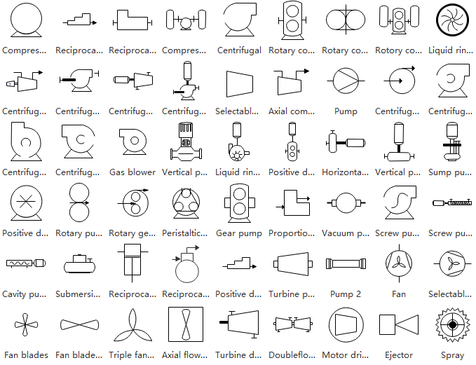
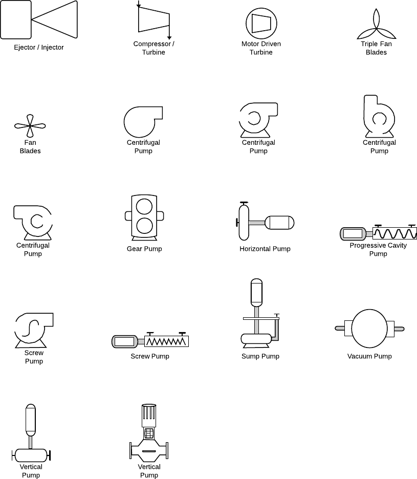
Piping and Instrument Diagram Standard Symbols Detailed Documentation provides a standard set of shapes & symbols for documenting P&ID and PFD, including standard shapes of instrument, valves, pump, heating exchanges, mixers, crushers, vessels, compressors, filters, motors and connecting shapes. Or Gate Not Gate Correcting Element Diamond
P&ID Symbols and Meanings EdrawMax Online
A piping and instrumentation diagram (P&ID) is defined as follows: A diagram which shows the interconnection of process equipment and the instrumentation used to control the process. In the process industry, a standard set of symbols is used to prepare drawings of processes.
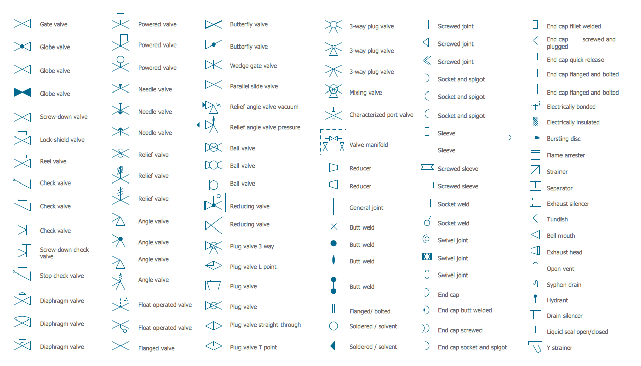
Kindly find in the image below P&ID symbols used in P&ID drawings for different valves and
What Does P&ID Mean? P&ID is an abbreviation meaning ' Piping and Instrumentation Diagram '. Piping and Instrumentation Diagrams are graphical representations of a process system. These are fundamental to every standardized engineering project. These two-dimensional diagrams function as a blueprint for the engineering system's design.
P&ID Symbols and Notation Lucidchart
2 minute read Want to make a P&ID of your own? Try Lucidchart. It's quick, easy, and completely free. Make a P&ID About P&ID symbols Piping and instrumentation diagrams, or P&IDs, are used to create important documentation for process industry facilities.